Introduction
Whether someone is wiring a home workshop, designing an industrial control panel, or troubleshooting a low-voltage LED system in a vehicle, the voltage drop calculator is one of the most essential tools in the electrician's arsenal. Voltage drop is more than just a number on a screen it is the difference between a motor running efficiently and burning out, between lights glowing at full brightness and flickering dimly, or between a safe wiring installation and a code violation.
This guide takes a thorough look at voltage drop, covering everything from the voltage drop formula and wire size chart to the voltage divider formula, the current divider formula, and the parallel resistor calculator. The content here is structured to benefit both beginners learning about circuits for the first time and experienced professionals who need a reliable reference they can trust.
By the end of this article, readers will understand how to calculate, interpret, and reduce voltage drop across wiring, resistors, and complex circuits and they'll know exactly which tool or formula to use for each situation.
Understanding Voltage Drop: The Basics
What Is Voltage Drop?
Voltage drop refers to the reduction in electric potential (voltage) that occurs as current travels through a conductor or component. This happens because no conductor is a perfect transmitter of electricity every wire, resistor, and connection has some resistance, and that resistance consumes a portion of the available voltage according to Ohm's Law.
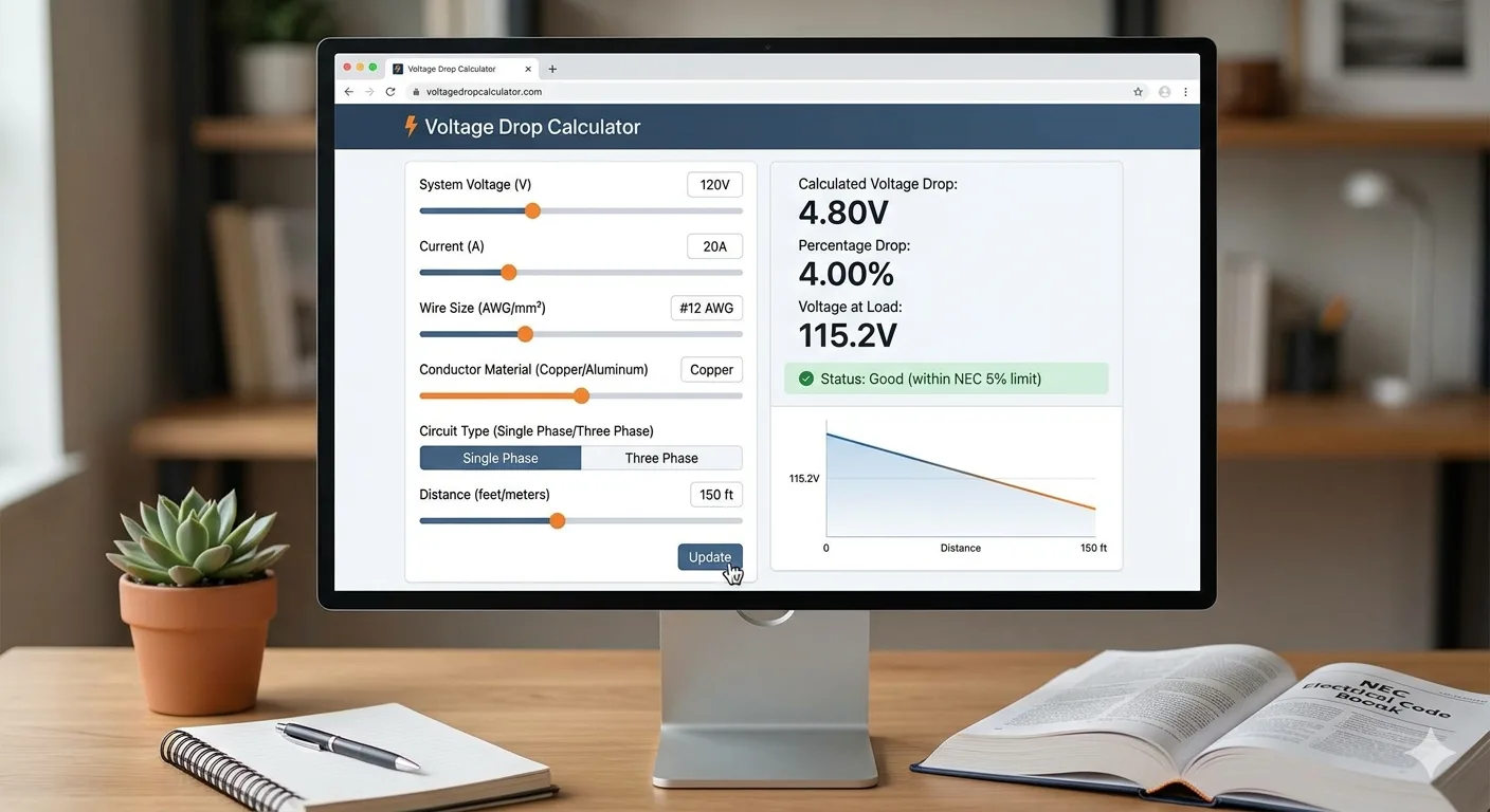
When considering how much voltage drop is acceptable, the NEC (National Electrical Code) provides a helpful benchmark. The code recommends keeping voltage drop to a maximum of 3% for branch circuits and a combined maximum of 5% for feeders and branch circuits together. So, for a standard 120V branch circuit, the acceptable voltage drop would be no more than 3.6 volts.
Voltage Drop in Series vs. Parallel Circuits
Understanding voltage drop in a series circuit is one of the most important concepts in basic electronics. In a series circuit formula, the total voltage supplied by the source equals the sum of all individual voltage drops across each component. If a series circuit has three resistors, each carrying current, the voltage drop across each resistor adds up to the source voltage.
In contrast, voltage drop in a parallel circuit behaves differently. In a parallel configuration, the voltage across each branch is equal to the source voltage. This is why knowing how to calculate voltage drop in a series parallel circuit one that combines both topologies becomes a critical skill for anyone working with complex systems.
For those wondering how to calculate voltage drop in a parallel circuit, the answer is straightforward: the voltage drop across each parallel branch is the same as the supply voltage. The current, however, is divided among the branches based on their individual resistances which is precisely where the current divider rule comes in.

Does Voltage Drop Across a Resistor?
Does voltage drop across a resistor? Yes, absolutely. Every resistor in a circuit creates a voltage drop proportional to the current flowing through it and the resistance value. The voltage drop across resistor formula is simply derived from Ohm's Law: V = I × R. If 2 amperes flow through a 10-ohm resistor, the voltage drop across that resistor is 20 volts.
The voltage drop across a single resistor is easy to calculate when the current is known. But when current is not given, a voltage drop calculator resistor tool or the full circuit analysis approach becomes necessary. This is where combining the voltage divider concept with Ohm's Law gives engineers the answers they need.
Using a Voltage Drop Calculator
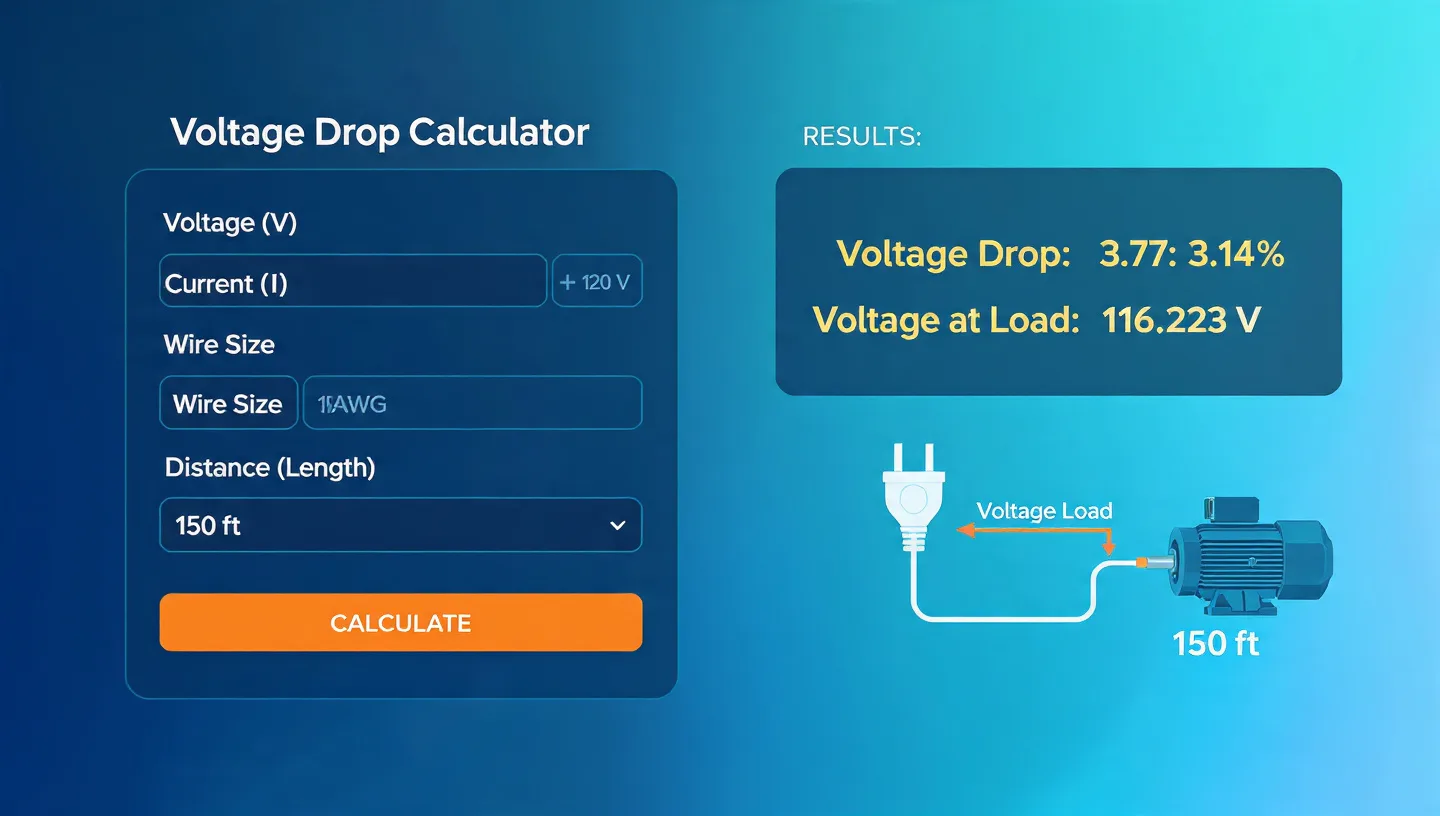
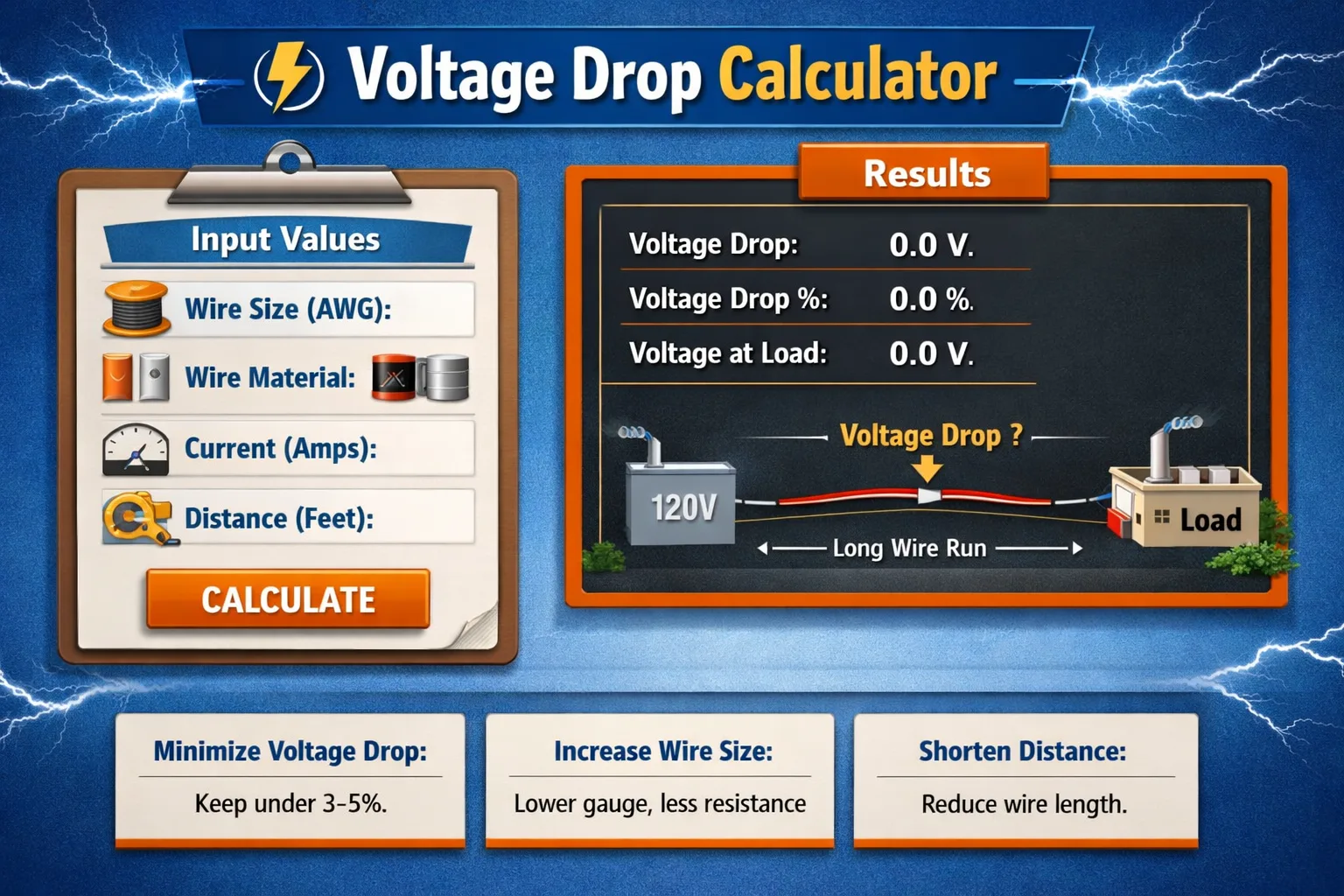
What a Voltage Drop Calculator Does
A voltage drop calculator takes several inputs such as the source voltage, conductor material (copper or aluminum), wire gauge, circuit length, and current load and computes how much voltage will be lost along the run. The result helps engineers and electricians determine whether the existing wire size is adequate or if a larger conductor is needed.
Different tools exist for different applications. A DC voltage drop calculator is designed for direct-current systems, such as solar panel installations, battery systems, and automotive wiring. An AC voltage drop calculator (also referred to as an a c voltage drop calculator) is used for standard household and commercial AC systems. When running calculations for three-phase power systems, a voltage drop calculator 3 phase is the appropriate choice.
Southwire Voltage Drop Calculator
Among the most widely used professional tools in North America is the Southwire voltage drop calculator. Developed by Southwire Company, this calculator follows NEC guidelines and allows users to calculate voltage drop for a wide range of scenarios — from single-family residential wiring to complex commercial and industrial applications. The Southwire voltage drop calculator 240v version is particularly useful for large appliance circuits and sub-panel feeds.
For those who prefer mobile solutions, the Southwire voltage drop calculator app brings the same power to smartphones and tablets. Alongside it, the Southwire conduit fill calculator helps users determine how many conductors can be safely placed inside a conduit — another essential NEC compliance tool.
NEC Voltage Drop Calculator
The NEC voltage drop calculator is built around the requirements of the National Electrical Code. It's used by inspectors, contractors, and engineers to verify compliance before installations are approved. This type of calculator generally factors in conductor type, ambient temperature, conduit fill, and the type of load being served. The NEC voltage drop chart provides a tabular reference that works alongside the calculator, making it easy to cross-check results.
Wire Size Calculator and Voltage Drop Calculator Wire Size
One of the most common questions professionals ask is, "What wire size do I need for this circuit?" The wire size calculator answers that question by factoring in current load, voltage, distance, and acceptable drop percentage to recommend the appropriate AWG (American Wire Gauge) or metric size.
When the goal is specifically to select a wire based on an allowable voltage drop budget, a voltage drop calculator wire size tool becomes the preferred resource. These calculators are common in both residential and commercial electrical design workflows.
For DC systems, the wire size calculator dc and wire size calculator 12v are go-to resources in automotive and marine electrical work. For AC systems, the wire size calculator ac including the wire size calculator ac 240v variant covers residential and light commercial scenarios. A wire size calculator app is available for mobile use in the field, while a wire size calculator in mm2 accommodates international metric standards.
Voltage Drop Calculator: 12V and Other DC Systems
Low-voltage DC applications demand extra attention to voltage drop because the margin is much tighter. In a 12-volt system, even a 0.5-volt drop can represent over 4% of the supply voltage — already approaching the acceptable threshold. The voltage drop calculator 12v and 12v voltage drop calculator tools help users keep their systems within the acceptable voltage drop 12v range, which is generally 3% or less for sensitive electronics.
Similarly, the 24v voltage drop calculator and its close cousins the 24v dc voltage drop calculator and 24vdc voltage drop calculator are heavily used in commercial HVAC controls, access control systems, and industrial sensors where 24VDC is the standard supply voltage.
For those planning longer cable runs in 12V systems, resources like the 12v voltage drop over distance chart and the 12v dc power drop max cable distance chart provide quick lookups for common wire sizes and current loads. The 12v voltage drop chart and voltage drop chart 12v (sometimes labeled 12v dc voltage drop chart) are essential references for installers and designers alike.
Voltage Drop Calculator App and Software
For professionals who need to work on the go, a voltage drop calculator app provides instant results without needing to pull up a browser. Several software platforms also offer voltage drop calculation software free download options, making professional-grade analysis accessible to smaller contractors and independent electricians. For those who prefer spreadsheet-based tools, voltage drop calculation in excel and the voltage drop calculator excel format allow customized calculations with adjustable inputs. A ready-made cable voltage drop calculation excel sheet or voltage drop calculation formula excel sheet speeds up design work considerably.
Voltage Drop Formulas Explained
The Voltage Drop Formula
The voltage drop formula for a single-phase AC or DC circuit is:
VD = (2 × K × I × L) / CM
Where VD is voltage drop, K is the resistivity constant (12.9 for copper, 21.2 for aluminum), I is the current in amperes, L is the one-way length of the circuit in feet, and CM is the circular mil area of the conductor.
A simplified voltage drop formula version uses Ohm's Law directly: VD = I × R, where R is the resistance of the wire run (both ways). This basic form is used in most voltage drop calculator resistor tools for electronic circuit analysis.
Voltage Drop Formula for Single Phase
The voltage drop formula for single phase systems is the same as described above: VD = (2 × K × I × L) / CM. The factor of 2 accounts for the current traveling to the load and returning through the neutral conductor. This formula is at the heart of every ac voltage drop calculator built for residential and light commercial applications.
Voltage Drop Formula 3 Phase
For three-phase systems, the voltage drop formula 3 phase differs slightly:
VD = (√3 × K × I × L) / CM
The square root of 3 (approximately 1.732) replaces the factor of 2 used in single-phase calculations, reflecting the geometric relationship between the phases. This is the formula behind every voltage drop calculator 3 phase tool. A full 3 phase voltage drop calculation formula breakdown, including the 3 phase voltage drop calculation formula pdf and 3 phase voltage drop calculation formula excel resources, helps engineers document and verify their work. The maximum voltage drop allowed 3 phase is generally 5% combined (feeder plus branch circuit), per NEC recommendations.
Voltage Drop Formula for Cable
In cable sizing and power distribution, the voltage drop formula for cable uses the specific resistance per unit length of the cable type (in mΩ/m or similar units) multiplied by the current and cable length. The voltage drop calculation for cable is a standard exercise in electrical engineering design, and the voltage drop calculation formula for cables is taught in every electrical engineering curriculum. Resources like the voltage drop calculation for cable pdf and example of voltage drop calculation and cable selection pdf serve as practical references in the field.
The voltage drop formula for 3 phase cable applies the same three-phase multiplier. Professionals working with international standards will find that the cable size and voltage drop calculation methodology varies by region, so it's important to use country-specific references when working outside North America.
DC Voltage Drop Formula
The dc voltage drop formula is identical in form to the single-phase AC formula (since DC has no reactive component): VD = I × R, or VD = (2 × ρ × L × I) / A, where ρ is resistivity, L is length, I is current, and A is cross-sectional area. A 12v dc voltage drop calculator and dc voltage calculator typically implement this formula with inputs in user-friendly units. The voltage drop formula 2kil is a simplified field approximation used in some DC wiring guides.
Voltage Drop Formula AC
The voltage drop formula ac for resistive loads is the same as the DC formula. However, for inductive or capacitive loads, the formula must account for the power factor and impedance of the circuit, not just resistance. This makes how to calculate voltage in a series circuit with reactive components more complex. Advanced AC analysis uses phasors and complex impedance to determine voltage drops accurately.
A voltage drop formula series circuit for pure resistive AC loads sums the individual resistive drops. The voltage drop formula parallel circuit confirms that the voltage is constant across all parallel branches, while the current splits according to each branch's impedance.
Voltage Divider: Formula, Rule, Circuit, and Calculator
Voltage Divider Formula
The voltage divider formula is one of the most frequently used expressions in electronics. It defines the output voltage of a resistive divider network:
Vout = Vin × (R2 / (R1 + R2))
This formula is the foundation of countless analog circuit designs, from sensor signal conditioning to reference voltage generation. The voltage divider formula for 3 resistors and voltage divider formula for multiple resistors extend this concept to more complex networks. For three resistors in series, the voltage across the lowest resistor is Vout = Vin × (R3 / (R1 + R2 + R3)).
A voltage divider formula series circuit places resistors in series so that the supply voltage is distributed proportionally. The voltage divider formula derivation shows how this expression is derived directly from Ohm's Law and Kirchhoff's Voltage Law, confirming its universal applicability.
Voltage Divider Rule
The voltage divider rule (VDR) is a shortcut for finding the voltage across any resistor in a series string without calculating the current explicitly. It states that the voltage across a resistor is equal to the total supply voltage multiplied by the ratio of that resistor's value to the total series resistance. The voltage divider rule formula is therefore:
VR = Vsupply × (Rn / Rtotal)
The voltage divider rule formula in series circuit is particularly useful when designers need to verify voltage levels at different nodes quickly. The voltage divider rule in series circuit applies whenever resistors are connected end-to-end with the same current flowing through all of them. The voltage divider rule derivation ties back to Kirchhoff's Voltage Law, which states that the algebraic sum of all voltages around a closed loop equals zero.
Interestingly, there is also a voltage divider rule formula in parallel circuit application, which is less commonly discussed. In this case, the rule applies to the series elements that feed the parallel combination, confirming that the full supply voltage appears across the parallel group.
Voltage Divider Circuit
A voltage divider circuit typically consists of two resistors connected in series between a supply voltage and ground. The output is taken from the junction between the two resistors. This simple configuration is found in everything from volume knobs to transistor biasing networks.
The voltage divider circuit diagram shows R1 connected from Vin to the midpoint, and R2 from the midpoint to ground. The voltage divider 3 resistors version simply extends this by adding a third resistor in the series chain, allowing for two intermediate output voltages. A voltage divider breadboard prototype is often the first circuit a student assembles in an introductory electronics lab.
The voltage divider resistor selection process involves choosing R1 and R2 values that achieve the desired output voltage while keeping current draw at an acceptable level. A voltage divider resistor calculator automates this process, and a voltage divider calculator with load accounts for the effect of a load resistance connected at the output which changes the effective R2 value and shifts the output voltage.
Voltage Divider Calculator
A voltage divider calculator allows users to input the supply voltage and two (or more) resistor values, then instantly computes the output voltage at each node. The voltage divider calculator 3 resistors, voltage divider calculator 4 resistors, voltage divider calculator 5 resistors, and voltage divider calculator 6 resistors variants handle increasingly complex resistive ladder networks.
A voltage divider calculator 2 resistors is the most basic version and is sufficient for most practical applications. A voltage divider calculator parallel handles situations where one of the legs contains a parallel resistor combination, and the voltage divider current calculator adds current draw to the output data. A resistor divider calculator standard values is especially useful for engineers who need to select from the E12 or E24 series of standard component values.
The resistor voltage divider calculator and the voltage divider rule calculator are closely related tools — the former focuses on resistor values and their ratios, while the latter applies the voltage divider rule directly to find node voltages in series circuits.
Voltage Divider Rule and Current Divider Rule
Understanding the relationship between the voltage divider rule and current divider rule is fundamental to circuit analysis. While the voltage divider rule applies to series circuits (same current, split voltage), the current divider rule applies to parallel circuits (same voltage, split current). Together, they cover the two most common circuit configurations encountered in real-world designs.
Current Divider: Formula, Rule, and Circuit
Current Divider Formula
The current divider formula calculates how current splits between parallel branches. For a two-branch parallel circuit, the current through branch 1 is:
I1 = Itotal × (R2 / (R1 + R2))
Notice that the formula uses the opposite resistor in the numerator higher resistance branches carry less current, and lower resistance branches carry more. The current divider equation with 3 resistors extends this to a more general case using the conductance (reciprocal of resistance) of each branch.
Current Divider Rule
The current divider rule states that in a parallel circuit, the current through any branch is equal to the total current multiplied by the ratio of the equivalent resistance of the remaining branches to the total resistance of all branches. For a simple two-resistor parallel network, this simplifies to the formula above.
Understanding how to calculate current in a series circuit is actually simpler than in a parallel circuit in a series connection, the same current flows through every component. The challenge in series circuits is knowing how to calculate current through a resistor in series when multiple voltage sources or resistors are present, which requires applying Kirchhoff's laws or superposition.
The voltage drop in parallel circuit analysis confirms what theory predicts: the voltage is equal across all parallel branches, and the drops across series elements (wiring, fuses, switches) are where the real losses occur. Professionals who need to know how to calculate voltage drop in cable and how it affects downstream devices will find this understanding essential. A voltage divider formula parallel circuit approach is sometimes used to model the interaction between the cable's series resistance and the parallel load treating the cable as the upper resistor and the load as the lower resistor in a divider network. A simpler model uses only two resistors, reflecting the voltage divider 2 resistors classic configuration.
Current Divider Circuit
A current divider circuit is the dual of the voltage divider instead of splitting voltage across series resistors, it splits current across parallel resistors. A current divider calculator simplifies this process by computing branch currents automatically. For complex networks, a parallel circuit current calculator with voltage tool handles the interplay between current and voltage in multi-branch systems.
Knowing how to calculate current across a resistor in parallel is also important for troubleshooting if one branch carries significantly more current than expected, that often points to a fault or component failure in another branch.
Resistor Calculations: Series, Parallel, and Combinations
Parallel Resistor Calculator and Formula
The parallel resistor calculator computes the equivalent resistance of two or more resistors connected in parallel. The parallel resistor formula is:
1/Rtotal = 1/R1 + 1/R2 + 1/R3 + ...
Or equivalently, for two resistors: Rtotal = (R1 × R2) / (R1 + R2). The 2 resistors in parallel formula and 3 resistors in parallel formula follow directly from this. A 3 parallel resistor calculator and a parallel resistor calculator reverse (which finds one unknown resistor value given the target equivalent resistance) are available in online tools for quick design work.
A parallel resistor Voltage Drop Calculator combines Ohm's Law with parallel resistance to find the voltage drop across the entire parallel combination. This is particularly useful in power electronics where heat dissipation and current sharing between parallel components must be carefully managed.
Voltage Drop Across Resistor in Parallel
The voltage drop across resistor in parallel is one of the most straightforward results in circuit analysis: the voltage is the same across every resistor in a parallel group. However, the voltage drop across resistors in parallel from the perspective of current sharing shows that lower-resistance paths carry proportionally more current which affects heat dissipation and component ratings.
A voltage drop across resistor calculator, resistor voltage drop calculator, and voltage drop resistor calculator all provide the same core function: given current and resistance (or given voltage and resistance for current), calculate the voltage drop. The voltage across resistor calculator extends this by allowing the user to compute voltage at any node in a circuit. The ac voltage drop resistor calculator applies the same logic to AC resistive circuits.
For those who need to find how to calculate voltage drop across a resistor without current explicitly known, the voltage drop across resistor without current approach uses the voltage divider formula: if the total resistance and supply voltage are known, the drop across any individual resistor can be found directly.
Series Resistor Calculator
The series resistor calculator adds up resistor values to find total resistance. In a series connection, Rtotal = R1 + R2 + R3 + ..., making it one of the simplest calculations in electronics. The series parallel resistor calculator handles circuits where both topologies appear together which is the most common situation in real-world electronics.
Understanding how to calculate voltage drop in a series circuit and how to calculate voltage across a resistor in series are companion skills. The first requires knowing the total circuit resistance and current; the second applies the voltage divider rule to find individual drops. The voltage drop in series circuit calculation is foundational in digital logic supply design, where power rail integrity is critical.
Voltage Drop Across Resistor in Series
When calculating voltage drop across resistor in series, the formula is V = I × R for each element. The total of all drops must equal the supply voltage, as mandated by Kirchhoff's Voltage Law. Tools that handle calculating voltage drop across a resistor in series parallel and calculating voltage drop across a resistor in series-parallel circuits use mesh analysis or node voltage methods when the topology becomes too complex for simple rules.
For circuit board work, how to test a resistor on a circuit board is a practical troubleshooting skill. The dc voltage drop resistor calculator helps verify expected versus measured voltage drops when validating a PCB design.
Wire Size Charts, Voltage Drop Charts, and Reference Tables
Wire Size Chart
The wire size chart is one of the most important references in electrical work. It lists wire gauges (AWG or metric), their corresponding current capacities (ampacity), and their resistance per unit length. Installers use this chart to select the correct conductor for a given load, while designers use it as a starting point before performing voltage drop calculations.
For metric applications, the wire size calculator in mm2 and related resources provide equivalent data in square millimeters, which is the standard in most countries outside the United States.
Voltage Drop Chart
A voltage drop chart provides pre-calculated voltage drops for common combinations of wire gauge, current, and circuit length. These charts save time during design reviews and site surveys, eliminating the need to run calculations for every scenario. A voltage drop table presents the same data in tabular form, and a voltage drop table pdf version makes it easy to print and carry to the job site.
Specialized charts include the voltage drop chart 240v and voltage drop chart 120v for standard North American voltages. The dc voltage drop chart and voltage drop chart pdf cover DC applications, while the ac voltage drop chart applies to AC systems. For NEC compliance, the voltage drop table nec and NEC voltage drop chart align with code requirements.
7.3 Fuse Voltage Drop Chart
A fuse voltage drop chart helps automotive and electronics professionals understand the voltage loss introduced by fuses in a circuit. Even a properly rated fuse has measurable internal resistance, and in low-voltage DC systems, this drop can be significant. The standard fuse voltage drop chart, fuse voltage drop chart pdf, and fuse voltage drop chart mini fuse are common references in 12V automotive design. Knowing the expected fuse drop helps in calculating the total system voltage budget.
Voltage Drop Distance Chart
The voltage drop distance chart and 12v dc power drop max cable distance chart help installers quickly determine the maximum wire run length for a given gauge and current before exceeding the acceptable drop threshold. These charts are especially useful in outdoor lighting, irrigation control, and security camera installations where long cable runs are unavoidable.
The voltage drop calculation pec refers to calculations performed in accordance with the Philippine Electrical Code, which has its own voltage drop standards similar to, but distinct from, NEC guidelines.
Using a Multimeter to Measure Voltage, Current, and Resistance
How to Read Voltage with a Multimeter
Knowing how to read voltage with a multimeter is an indispensable hands-on skill. To measure voltage, a technician sets the multimeter to the appropriate voltage range (AC or DC), places the red probe on the positive terminal and the black probe on the reference or negative terminal, and reads the display. Voltage measurements are always taken in parallel with the component being measured.
How to Use a Multimeter for AC Current
Understanding how to use multimeter for ac current requires a different approach than voltage measurement. Most digital multimeters measure current by placing the probes in series with the circuit (breaking the circuit and inserting the meter). For higher AC currents, a clamp meter is often safer and more practical. Knowing how to read voltage with multimeter is equally important the meter is set to voltage mode, placed in parallel with the component, and the display gives the live voltage reading in volts.
Measuring Voltage Across a Resistor with Multimeter
For hands-on validation of calculated values, how to measure voltage across a resistor with multimeter is the go-to technique. The probes are placed across (in parallel with) the resistor, and the reading confirms whether the actual drop matches the theoretical value. How to measure current across a resistor with multimeter uses the series connection method and is useful for verifying current sharing in parallel branches. How to measure node voltage with multimeter involves placing the black probe at the circuit reference (ground) and the red probe at the node being measured.
Multimeter Resistance Range and Advanced Measurements
The multimeter resistance range setting allows direct measurement of component resistance. It's important to measure resistance with power removed from the circuit otherwise, voltage in the circuit will interfere with and potentially damage the meter. This technique is used in how to calculate voltage drop across one resistor verification exercises and to identify shorted or open components.
The how to measure 12 volt amps with a multimeter question comes up frequently in automotive and RV electrical work. The process involves setting the meter to DC amps mode and placing it in series with the load. For large currents above the meter's ampere rating, a clamp meter or shunt resistor method is safer.
Power Calculations: AC Power, DC Motor Power, and Voltage-Current
AC Power Calculator
An AC power calculator computes real power (watts), apparent power (volt-amperes), and reactive power (VARs) for AC circuits. For resistive loads, real power = V × I. For inductive or capacitive loads, the power factor must be included: P = V × I × cos(θ). This is important context for understanding voltage drop, since inductive loads draw more current than their watt rating suggests.
Power Voltage Current Calculator
A power voltage current calculator is a multi-function tool that applies Ohm's Law and Joule's Law to compute any one of power, voltage, current, or resistance when the other two are known. This calculator is foundational in both basic electronics education and professional design work.
DC Motor Power Calculation Formula
The dc motor power calculation formula relates electrical power input to mechanical power output through the motor's efficiency rating. Electrical input power = V × I, and mechanical output power = Torque × Angular velocity. Calculating voltage drop in motor circuits is especially important because voltage reduction directly reduces motor torque and can lead to stall conditions in undersized wiring scenarios.
Calculate Current from Power and Voltage 3-Phase
For three-phase systems, the formula to calculate current from power and voltage 3-phase is: I = P / (√3 × V × PF), where P is total real power in watts, V is line-to-line voltage, and PF is the power factor. This formula is used as a starting point in three-phase voltage drop calculations, since the current value feeds directly into the voltage drop computation.
Read More : BMI Calculator
Common Questions About Voltage Drop and Resistor Circuits
How to Find VR1 in a Parallel Circuit
A question that appears frequently in student forums is how to find VR1 in a parallel circuit. The answer is straightforward: in a parallel circuit, the voltage across every branch (including the resistor labeled VR1) equals the supply voltage. This is one of the defining characteristics of parallel circuits and is the reason parallel wiring is used for home electrical systems every outlet receives the full voltage regardless of how many devices are connected.
How to Calculate Voltage Drop Across a Resistor in Parallel
For those seeking how to calculate voltage drop across a resistor in parallel, the process is to identify the voltage across the parallel network (which equals the supply voltage minus any series resistance drops) and recognize that this same voltage appears across each parallel resistor. Calculating voltage drop across a resistor in parallel and how to calculate voltage drop across a resistor in series are the two key skills that together cover almost every resistive circuit encountered in practice.
Voltage Drop Across Resistor Formula
The voltage drop across resistor formula is V = I × R. For more complex circuits where current is not immediately known, the voltage resistor calculator uses the complete circuit topology to determine the operating current before applying Ohm's Law. A single resistor voltage drop calculator is the simplest implementation just input the current and resistance, and the drop is calculated instantly.

Voltage Drop Calculator mm2
The voltage drop calculator mm2 is used in countries and industries that specify cable cross-sections in square millimeters. The formula and principles are identical to the AWG-based approach, but with metric units for cross-sectional area and resistance per meter. The voltage drop table for cables in mm2 provides quick reference data for common cable sizes used in European and international installations.
Voltage Drop Calculator for Parallel Circuit
A voltage drop calculator parallel circuit computes the voltage drop across the series elements that feed a parallel combination. Since the voltage across a parallel group is constant, the "drop" of interest is typically the series resistance of the supply wiring, connectors, and fuses that sit between the source and the parallel load. The parallel resistor voltage drop calculator focuses specifically on this series drop calculation.
Priority Wire and Specialty Voltage Drop Calculators
The priority wire voltage drop calculator is a tool offered by Priority Wire & Cable, designed for contractors who work with that manufacturer's products. Like the Southwire voltage drop calculator, it provides product-specific results that account for the actual measured resistance of that manufacturer's conductors which can differ slightly from NEC table values.
The wire size calculator southwire and voltage drop calculator Southwire variant are companion tools that help users select conductors from Southwire's product catalog. The wire size calculator ac 240v and the ac voltage drop calculator together provide a complete workflow for sizing conductors in large appliance and HVAC circuits.
Conclusion
From the foundational voltage drop formula to advanced tools like the Southwire voltage drop calculator, the NEC voltage drop calculator, and the voltage divider calculator, the world of voltage drop analysis is rich with resources designed to make electrical design safer, more efficient, and code-compliant. Whether a user needs a quick answer from a voltage drop chart, a detailed breakdown from a voltage drop calculation formula excel sheet, or a hands-on check with a multimeter, the tools and techniques are all within reach.
Understanding the wire size chart, the parallel resistor formula, the voltage divider rule, and the current divider formula together forms a complete picture of how voltage behaves in circuits from the simplest LED lighting project to the most complex three-phase industrial installation. Armed with these tools and formulas, any engineer, electrician, or enthusiast can design and troubleshoot electrical systems with confidence.
Also Checkout This Calculator : Snow Day Calculator